Version 7.0.0 Released
The KiCad project is proud to announce the release of version 7.0.0. KiCad 7 is a significant upgrade from KiCad 6, and comes with a number of exciting new features as well as improvements to existing features. The KiCad project hopes you enjoy version 7! Head to the KiCad download page to get your copy of the new version (note that some packages may still be in the process of being released at the time this announcement is published). Many thanks to all of the hard working folks who contributed to KiCad during the version 7 development cycle.
In accordance with the KiCad stable release policy, KiCad 6.x will no longer be maintained, and we will release bug fix versions of KiCad 7.x over the next year as we develop KiCad 8.
Version 7 Changes
KiCad 7 is a big release despite coming only a year after KiCad 6 — in the past year, developers have made more than 6000 commits, fixing over 1200 reported issues and adding a number of new features. This post highlights some of the larger new features, but there are many other smaller improvements and fixes made by almost 200 different contributors.
General
Release Schedule Change
While we missed our official annual release schedule date of January 31st, the annual release schedule went pretty well for our first attempt. We will continue to improve our stable release process going forward as we adapt to the new schedule.
Custom Fonts
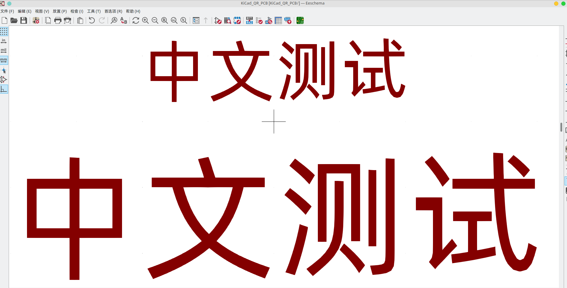
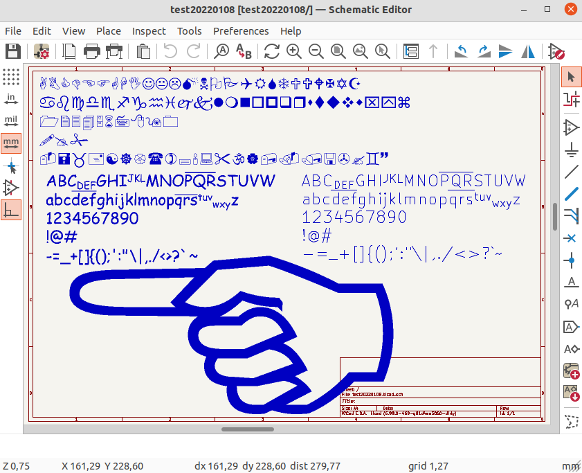
Custom font support is now available in the schematic, PCB, and worksheet editors to allow the use of any system font.
Text Boxes
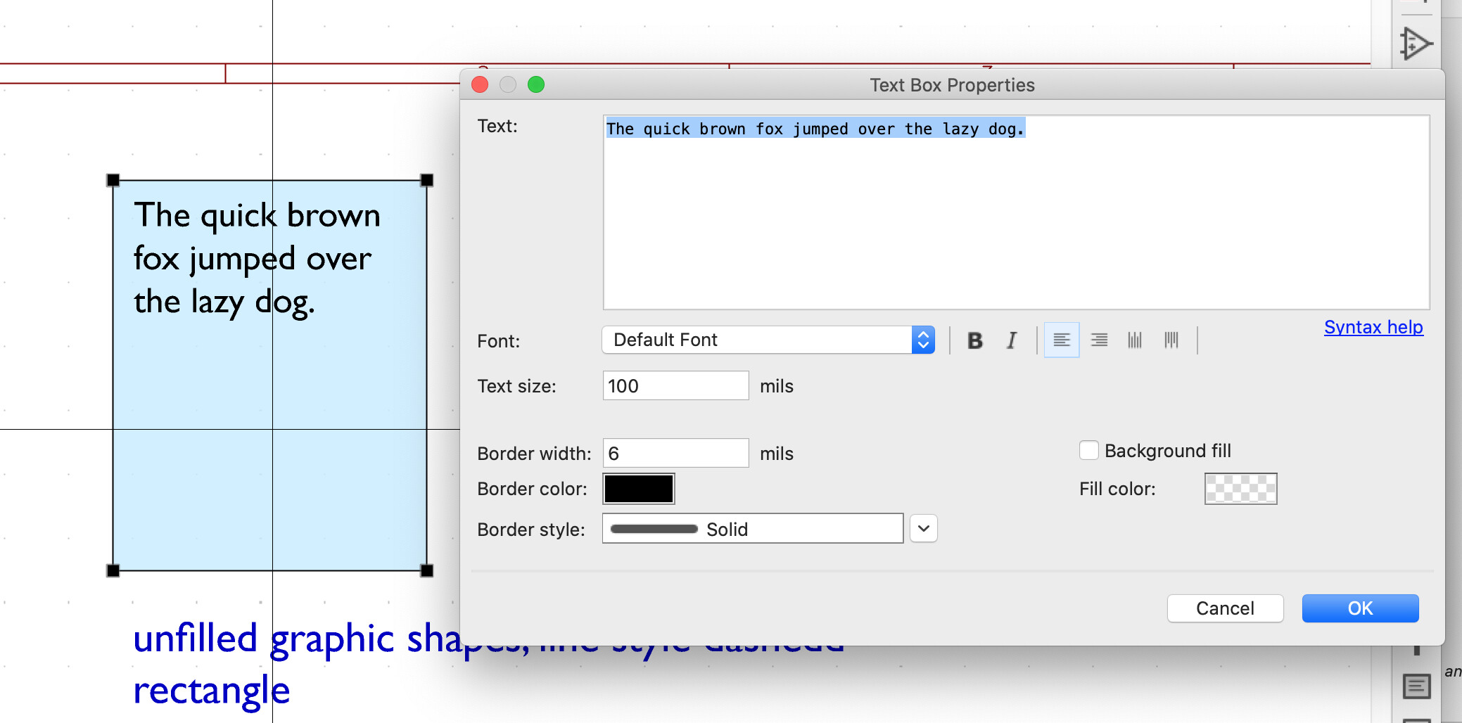
Text box support was added in both the schematic and PCB editors.
3Dconnexion SpaceMouse Support
3Dconnexion has contributed support in the schematic, symbol library, PCB, and footprint editors and 3D viewer for their line of SpaceMouse products. For those unfamiliar, 3D mice are alternative input devices that give a unique way of navigating both 3D and 2D canvases that some users find more ergonomic or intuitive than traditional mice. Users with a 3Dconnexion SpaceMouse may find this a welcome addition to KiCad’s capabilities to support their needs.
|
|
Currently this integration only works on Windows and macOS, where 3dconnexion provides their driver. The KiCad team is exploring integration with libspacenav to provide support for Linux and older SpaceMouse products that are no longer supported by 3Dconnexion. |
Sentry Crash Reporting Data Collection
Sentry is an open source platform to capture application events, crash dumps, and other analytics.
Both their hosted platform and the integrated SDK to handle crash reporting in C++ applications are open source on GitHub under the MIT license.
Sentry has sponsored KiCad by providing the core team with access to their SaaS platform to receive crash reports from KiCad users. During the Version 7 development cycle, KiCad has enabled opt-in Sentry crash reporting for Windows users (we are exploring expanding Sentry to more platforms in a future release). Users will be prompted once when KiCad is first started, and may choose whether or not to enable Sentry. Users may also switch Sentry data collection on or off at any time in the KiCad preferences.
Why do we want to collect data from users?
-
The primary use in KiCad will be to capture crash reports. If KiCad crashes, the Sentry tool will automatically send a report to the KiCad team containing information such as stack traces and core dumps.
-
In the future we may also use it to gather performance metrics of algorithms across the wider user base to answer questions such as "how long does it take on average to run the Fill All Zones command?".
What data is collected if Sentry is enabled?
-
A randomly-generated user ID (GUID) is created for each KiCad installation and is used to identify Sentry reports that come from the same installation (for example, if one user experiences a given crash three times).
-
This user ID can be reset at any time by the user through KiCad preferences.
-
Along with this user ID, Sentry collects crash dump information and extracts relevant portions such as call stacks and stack frames. The rest of the crash dump is discarded.
-
To aid in avoiding the collection of personally-identifying information (PII), all Sentry reports pass through a "sentry-relay" server owned by KiCad before being transmitted to the Sentry SaaS platform. This prevents user IP addresses from being disclosed to Sentry.
-
No KiCad design files are ever captured by Sentry.
More details about Sentry in KiCad
-
A new CMake variable,
KICAD_USE_SENTRY, has been added where a value of OFF will disable the inclusion of the Sentry SDK entirely. The current default value is OFF, as only Windows support is tested. -
Sentry will only store at most 1 raw crash dump per report for analysis.
-
Data in Sentry is retained for up to 90 days, and then is deleted.
The introduction of Sentry resolves a long-standing desire of the KiCad team to capture crash dumps without user involvement, and the use of Sentry offers us a very easy solution to do it and help make KiCad better for everyone.
Throughout the development of KiCad 7, the Sentry tool has already proven its usefulness by allowing the development team to resolve over two dozen crash bugs that were not previously reported by users. We look forward to this feature allowing us to continuously improve KiCad’s reliability over time.
PCM Automatic Updates
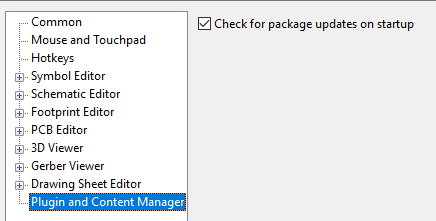
The Plugin and Content Manager now can automatically check if an updated version of an installed package is available and prompt the user to update. Content. Each time KiCad is launched, the plugin status is automatically queried in the background and displayed:

The automatic update checking behavior is opt-in and can be disabled.
Drag & Drop
Drag and drop handles have been added to various parts of KiCad that results in the following actions:
-
KiCad
-
Dragging a
kicad_proorprofile onto the project manager will open that project. -
Dragging a Gerber or Gerber Job file onto the project manager will open the Gerber Viewer with those files.
-
Dragging Eagle and Cadstar files will trigger an import of those files.
-
-
Schematic Editor
-
Dragging a
kicad_schfile onto the editor will append the schematic to the open design.
-
-
PCB Editor
-
Dragging a
kicad_pcbfile onto the editor will append the board to the open design.
-
-
Gerber Viewer
-
Dragging files onto the Gerber Viewer will open them.
-
-
Drawing Sheet Editor
-
Dragging a
kicad_wksfile onto the editor will open it.
-
macOS Apple Silicon support
KiCad now builds and can be packaged correctly as native Apple silicon processors (M1, M2, etc). This means that KiCad no longer has to run in emulation mode under the latest Apple hardware.
Command Line Interface
The separate kicad-cli binary has been implemented to allow scripting of
many of the KiCad editor outputs.
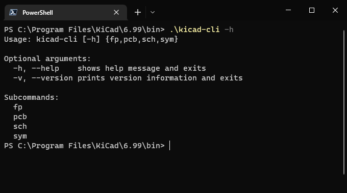
The KiCad command line interface brings all the necessary functions to automate export elements of schematic and pcb designs.
The currently available commands are:
kicad-cli sch export python-bom
kicad-cli sch export netlist
kicad-cli sch export pdf
kicad-cli sch export svg
kicad-cli pcb export drill
kicad-cli pcb export dxf
kicad-cli pcb export gerber
kicad-cli pcb export gerbers
kicad-cli pcb export pdf
kicad-cli pcb export pos
kicad-cli pcb export step
kicad-cli pcb export svg
kicad-cli fp export svg
kicad-cli fp upgrade
kicad-cli sym export svg
kicad-cli sym upgrade
kicad-cli version
You can use the -h argument to find out more about the command specific
options.
These changes have also enabled the STEP export to work headless on Linux,
unlike the original kicad2step binary.
Schematic and Symbol Editors
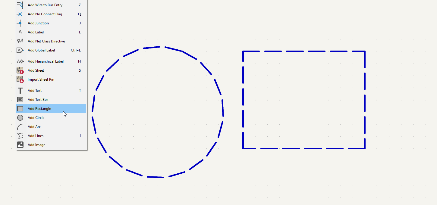
Support for a simple rectangle and circle primitives has been added to the schematic and symbol editors to round out the shapes already provided.
Orthogonal Dragging
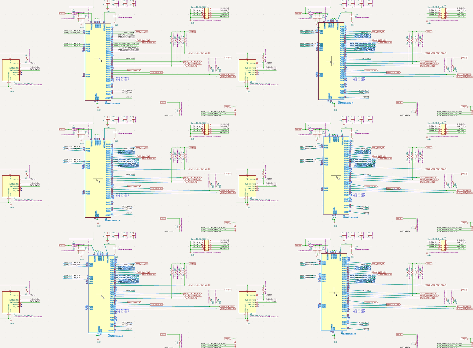
What is orthogonal dragging? In 6.0 and earlier, a drag operation in the Schematic Editor moves symbols while keeping wires attached to the symbol. However, it was a literal form of "attach" and wires would end up at odd angles and directions.
An example can be seen here of the old behavior:
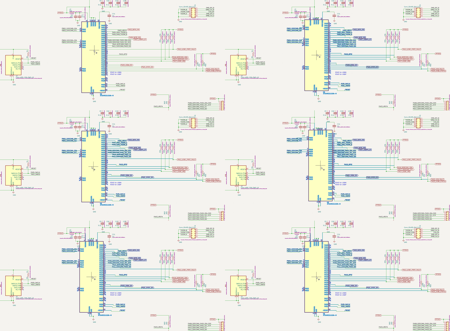
Orthogonal dragging forces all wires to extend and move forming right angles as expected for a schematic.
The new behavior is demonstrated in this animation:
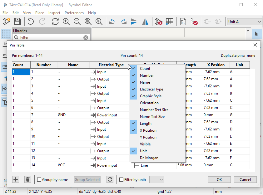
Symbol Editor Pin Table Enhancements
The Symbol Editor Pin Table got a number of new features, including the ability to:
-
Filter pins to a unit.
-
Change unit of a pin from the table.
-
Create or remove pins in a group symbol by adding/removing the pin number.
-
See the number of grouped pins.
Off Grid ERC Warnings
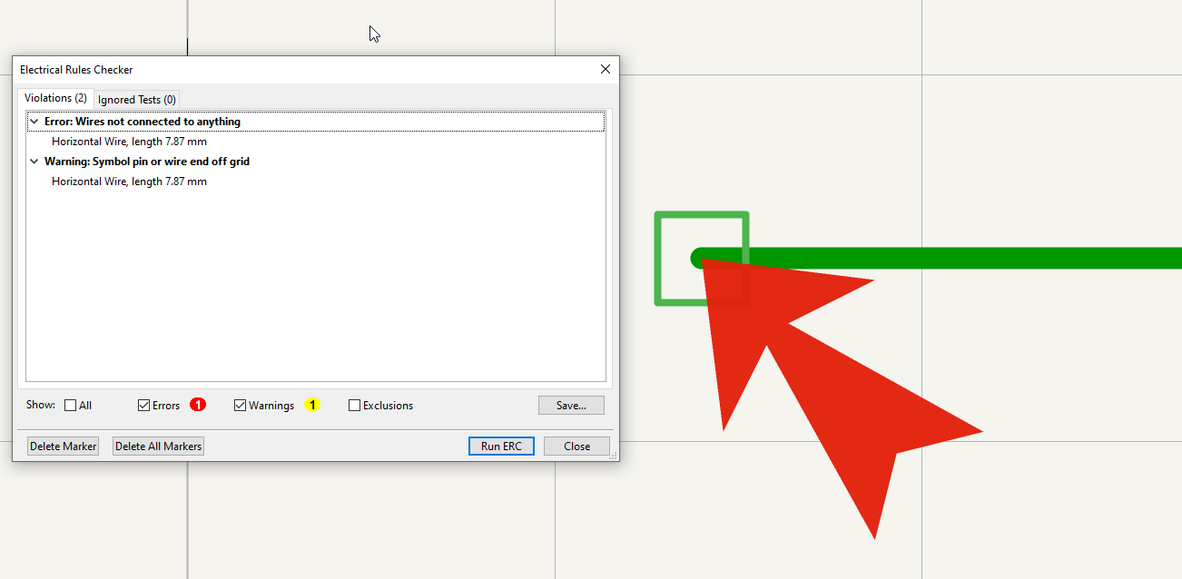
A new ERC check to warn when symbols are placed using an a incompatible grid. A grid mismatch can lead to situations where connections are not truly made and with a cascade of other issues such as pins being passive can lead to scenarios where you end up producing bad PCBs.
Wires at 45 Degree Angles
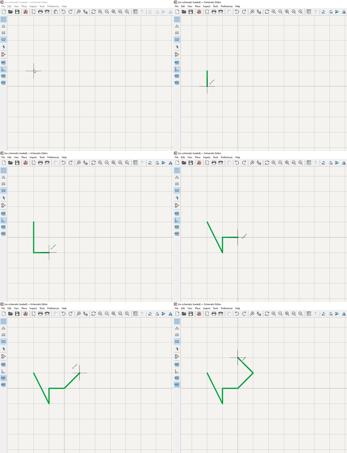
KiCad 6 originally included a single toggle between fixed right-angle wires and "any angle" mode. This change introduces a wire mode for 45 degree start and end to help in drawing crisp schematics.
You can start drawing a wire and hit the key combination of Shift + Spacebar
to cycle between wire drawing modes. Icons on the left side toolbar indicate
the current mode.
Do No Populate Support
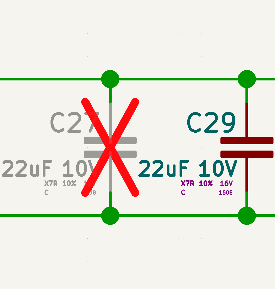
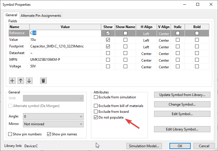
Support has been added for explicitly marking symbols in a schematic as Do Not Populate ("DNP"). The resulting symbols are grayed out in the schematic and marked with a red cross. DNP symbols are excluded from any KiCad-generated placement files.
Simulation Model Editor
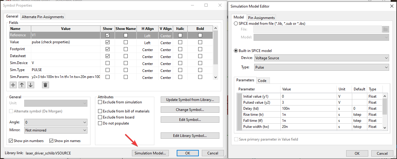
There is now a simulation model editor. This is a new dialog available as a "Simulation Model" button in the symbol properties of any schematic symbol. It allows configuration of simulation model parameters in a GUI rather than spice text inserted on schematic. The resulting configuration gets passed to the simulator as expected. Everything from configuring a symbol as "standard" spice model (resistors,caps,diodes,bjts) to assigning custom models in libraries (it will even load the library and let you select individual models contained within) is supported. It also allows for customization of the schematic pin to spice model pin mapping.
Database Libraries
A long requested feature by many users of KiCad has been the ability to link symbol selection to a database which is common in other schematic CAD tools. KiCad can now add connectivity to external databases via ODBC functionality across KiCad’s three main platforms.
The database library system allows creating a centralized database of symbol to footprint associations along with any metadata about your parts that can be shared across your schematics by you and others connected to the same database.
More information can be found in the KiCad database libraries documentation.
An ongoing forum discussion about the feature shows how some users are starting to make use of databases in their KiCad workflows.
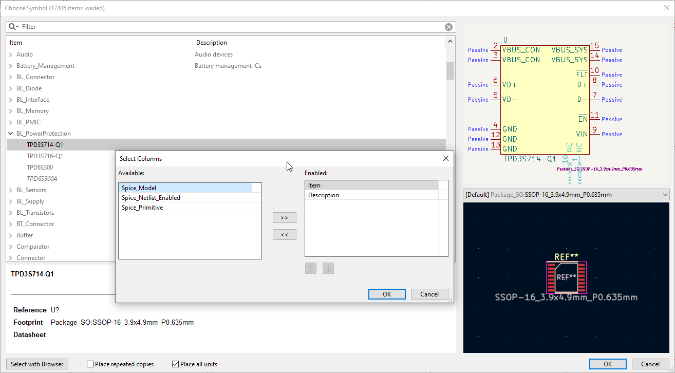
Dynamic field columns in symbol chooser
The database libraries support also introduced the ability to display and search custom fields in the symbol chooser.
Hyperlinks on Schematics
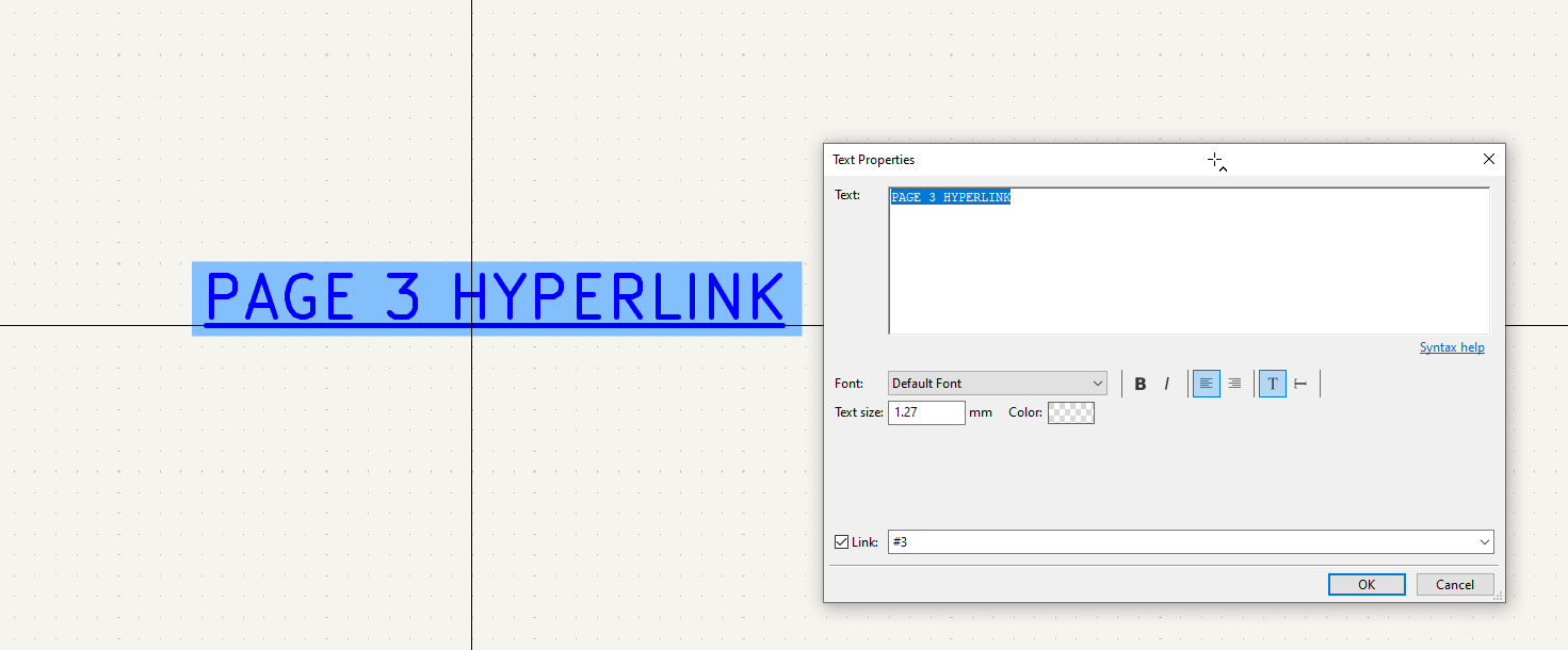
Hyperlinks are now supported inside schematics. This means a text object on a schematic page can detect if the text is a hyperlink property. Hyperlink text makes the text object become clickable.
Supported hyperlinks are:
-
http://
-
https://
-
file://
-
#:<pagenumber>(where <pagenumber> is any valid schematic page)
PDF Improvements
PDF Bookmarks (Table of Contents)
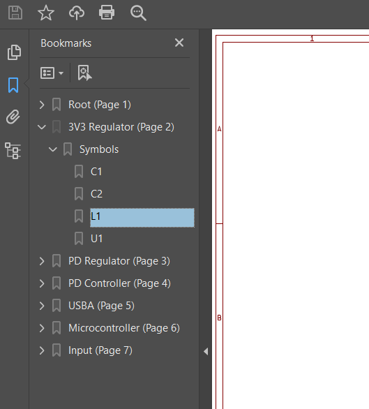
Support has been added for populating the bookmarks section (also known as the Table of Contents) of a PDF viewer with useful information.
A schematic PDF generated by the plot action in the schematic editor, will contain bookmarks populated with a list of sheets and links to symbols within the sheet. Clicking on items on the bookmark list will jump to the relevant page and location.
Embedded Symbol Information
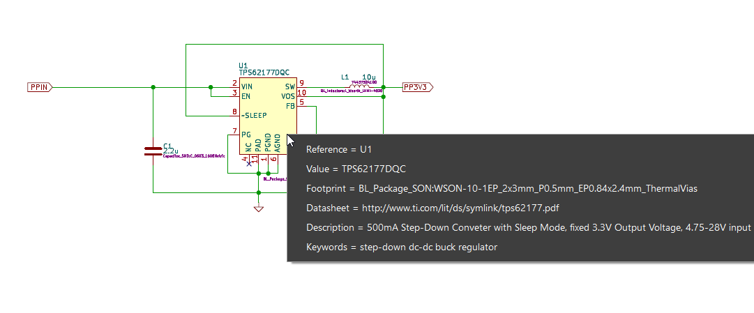
Support has been added the export of symbol information in schematics to the plotted PDF. This is a list of symbol field data displayed when the symbol is clicked in a PDF viewer. Unfortunately, the functionality required for this to work is implemented per PDF spec but support across PDF viewers is not consistent. Only Adobe PDF Reader/Acrobat are known to display the list correctly.
PDF Hyperlinks
Schematic hyperlinks are now embedded into the PDF and interactable.
This includes:
-
Hyperlinks between pages.
-
Hyperlinks to external URLs.
-
Sheet symbols link to datasheets.
Board and Footprint Editors
PCB Footprint Consistency Checking
A new optional check to determine if your board design has footprints that have deviated from the library they are linked to.

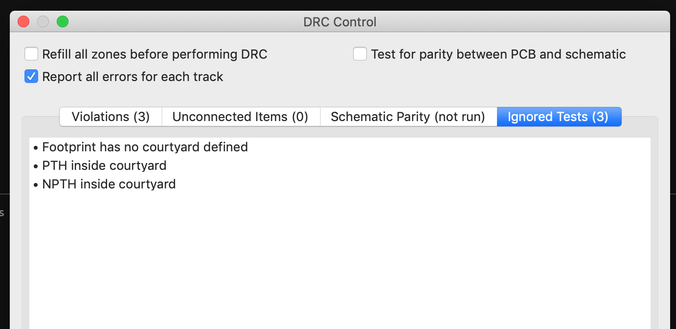
Ignored DRC Tests Tab
Ignored tests are now listed in their own separate tab.
Mechanical Clearance Rules.
Two new DRC rule constraints mechanical_clearance and mechanical_hole_clearance
have been add to the custom rules that the complement the clearance and
hole_clearance constraints.
While the later are not run on items of the same net, the mechanical_* versions are.
# Prevent solder wicking from SMD pads
(rule holes_in_pads
    (constraint mechanical_hole_clearance (min 0.2mm))
    (condition "B.Pad_Type == 'SMD'"))
Custom Rule Severities
Custom rule severities can now be defined per custom rule with possible values of
ignore, warning, error, and exclusion.
(rule "Via Hole to Track Clearance"
    (constraint hole_clearance (min 0.254mm))
    (condition "A.Type =='Via' && B.Type =='Track'")
    (severity warning))
Pad to Zone Rules
New custom rule constrains thermal_relief_gap, thermal_spoke_width and
zone_connection have been added for rule checking copper connections that
get generated between pads and zone fills.
The zone_connection constraint has valid options of solid, thermal_reliefs
or, none.
(rule heavy_thermals
   (constraint thermal_spoke_width (min 0.5mm))
   (condition "A.NetClass == 'HV'"))

# Don't use thermal reliefs on heatsink pads
(rule heat_sink_pad
    (constraint zone_connection solid)
    (condition "A.Fabrication_Property == 'Heatsink pad'"))
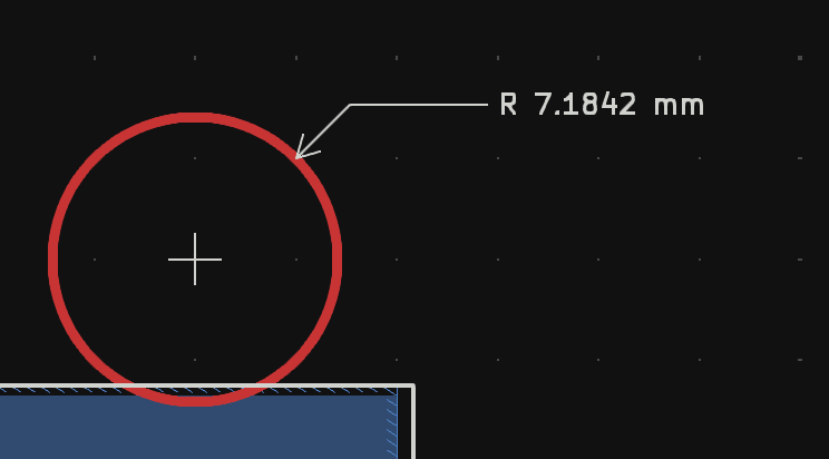
Radial Dimensions
Radial dimensions are now available.
Inverse Text Objects in PCB
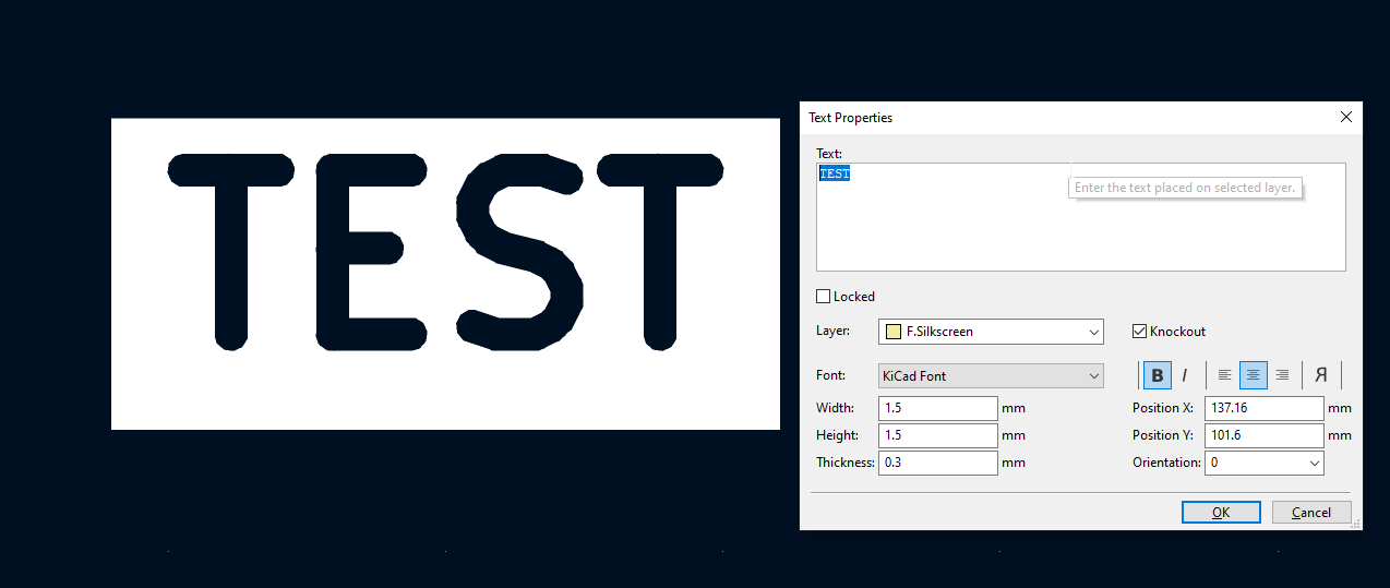
Text objects can now declare as "Knockout" meaning the text will subtract from a shaded box. This is useful for making more attention grabbing silkscreen.
Automatic Zone Filling
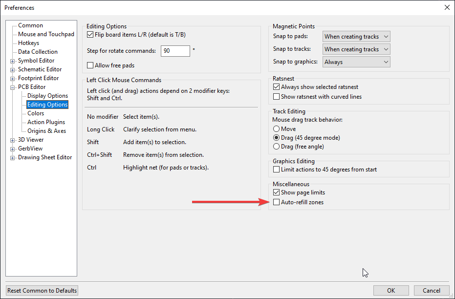
There is now a new option that will automatically refill zones when a board change is detected rather than requiring the user to trigger zone fills manually. This is enabled by default to help new users, but may be disabled in case it gets in the way for power users or those working on very large designs.
PCB Layout Tool Enhancements
Many ease of use enhancements have been made to the board and footprint editors.
Background Bitmaps.
A requested feature by users has been the ability to display an image in the background so that PCB traces and footprint layouts can be copied easily from some original reference PCB or footprint being reverse engineered.
Unroute Selected
It is now possible completely unroute a footprint.
Automatically Complete Trace Route
Traces can now be partially drawn and the board editor can complete the trace the rest of the way to the nearest ratsnest end. It will stop and force you to manually route if it can’t find a route.
Attempt to Finish Selection
Related to the trace route completion feature above, selected items can in the board editor can attempt to automatically route traces between them. It will iterate each unrouted part of the item and attempt to connect it to the nearest rats nest.
Search Panel
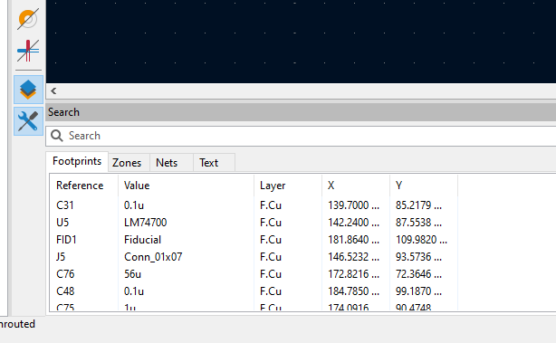
A new panel added to board editor enables typing query strings with wildcard s and filtering out objects on the design while displaying the remaining results in a list. The list can be clicked on to select objects on the editing canvas.
Properties Panel
A new properties panel is now available in the board editor.
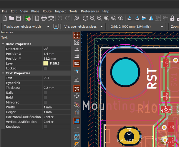
This panel allows quick access to many of the properties of objects, and allows you to edit multiple objects at the same time. Access to more properties will be added over time, and future KiCad releases will expand the properties panel to the schematic and library editors.
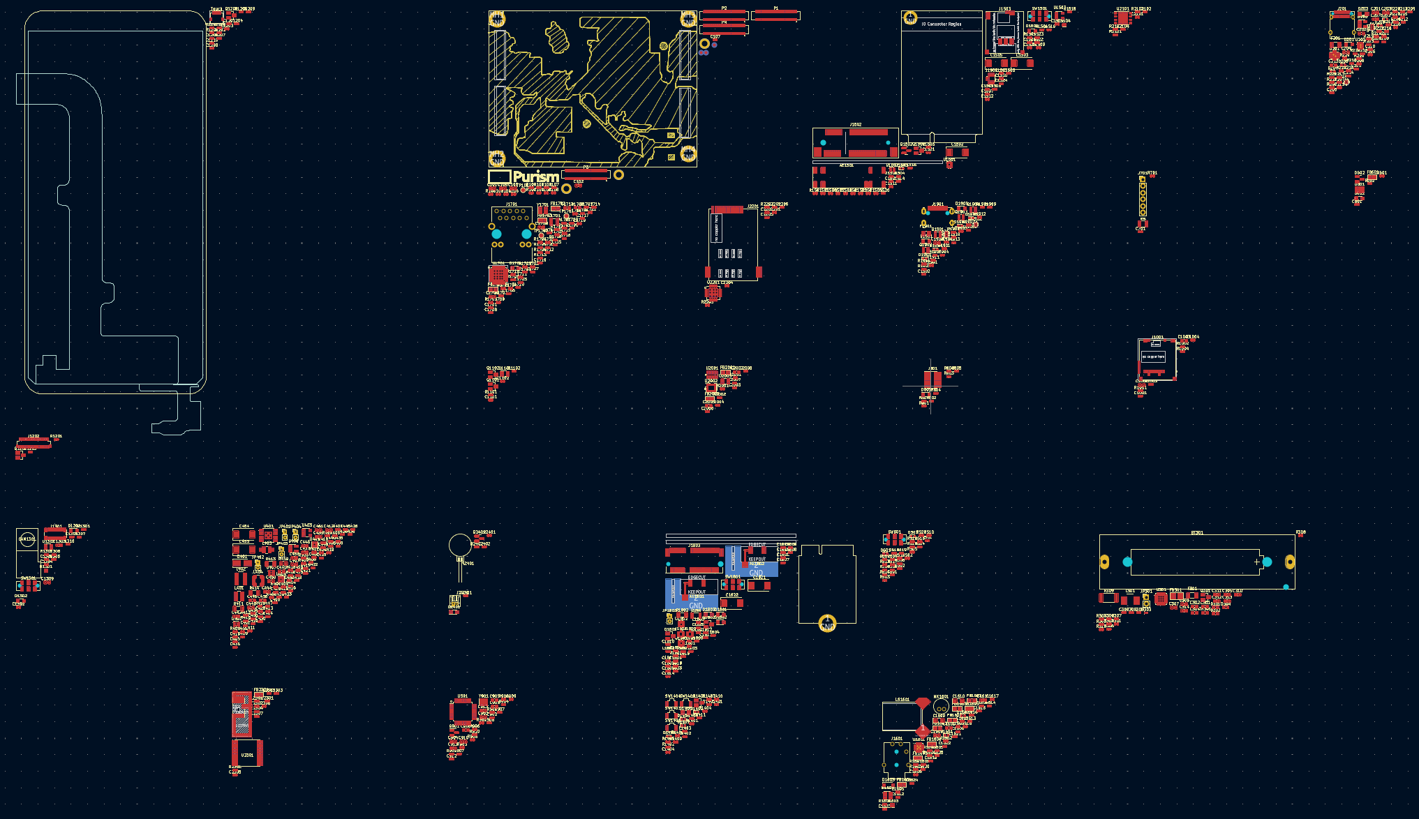
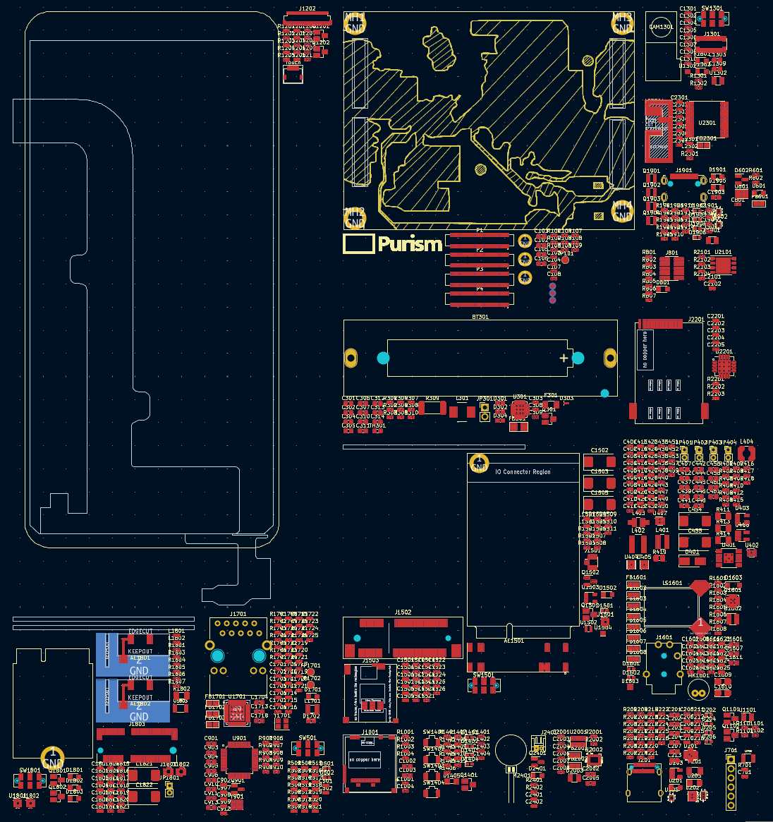
Improved Footprint Spread and Pack & Move Footprint Tool
The algorithm that placed footprints on the PCB was improved to result in a more compact layout.
Before the algorithm of this change:
After the algorithm of this change:
A powerful new tool was added that allows for a selection a logical portion of
a schematic in the schematic editor and with a new right click menu option or
the P hotkey in the board editor, selected symbol footprint can now use the
"Pack and Move" algorithm to create one compacted group rather than having to
manually locate and drag footprints in the board editor.
STEP Exporter Changes
The STEP exporter now uses the same PCB parsing engine as the rest of KiCad. This change now brings the addition relative 3d model paths to the footprint. Simply start the paths with the expected ./ or ../ and the 3D viewer and STEP exporter will attempt to find the model relative to the footprint file. This change should allow better portability of footprint libraries and 3d models.
The "3D Path Aliases" have been removed from KiCad. These were an independent system from the "Environment Variable" system also used for paths. It had it’s own file format and usage syntax which both introduced unexpected bugs. Unifying the system makes the usage of Environment Variables standard throughout KiCad. "3D Path Aliases" will be automatically migrated to an environment variable on launch. However, the alias may get renamed if the alias had characters beyond uppercase A-Z,0-9 and underscores due to the limitations of environment variables across platforms.
See Also
KiCad 6.0.11 Release
2023-01-26
The KiCad project is proud to announce the latest and most likely last series 6 stable release. The 6.0.11 stable version contains critical bug fixes and other minor improvements since the previous release.
KiCad Version 7 Release Candidate 1
2023-01-08
The KiCad project is excited to announce the first release candidate for the upcoming version 7 stable release. Version 7 will contain many new features compared to the current version 6 release. Please consider giving 7.0.0-rc1 a try to discover any additional issues so they can be fixed before release at the end of January. Thank you to everyone who contributed to version 7. How to Download Release Candidate Builds The release candidate packages can be found in the "Nightly Development Builds" folder on the KiCad Download Page.
